BASICS OF USE
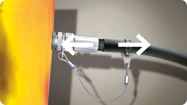
STEP 1: Disengagement
The Stopflex system does not operate during the disengagement of the flexible hose, but, if applied correctly, it ensures that the hose is fully disengaged from the ferrule restraining it.
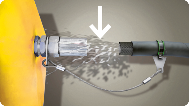
STEP 2: Release/Venting of pressure
During this step, the pressurised oil exits from the flexible hose. The hose begins to release the energy contained therein, and gains considerable velocity, triggering a hazardous “whip effect”, which is very dangerous to anyone or anything in its vicinity.
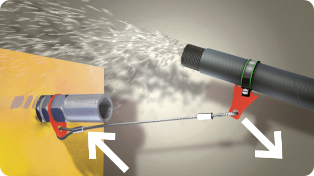
STEP 3: Restraint
Once the hose has been disengaged and the pressure released, the flexible hose can be restrained. This is when the Stopflex system gets into operation: the steel cable is tensioned and deformed while the plate cuts into the rubber of the hose, preventing the clamp, firmly attached to the hose, from disengaging. The hose clamp and plate start to deform in turn, elastically absorbing the force released from the travel of the flexible hose. This is a critical step which occurs within just a few seconds, during which the materials and components of the system, previously sized and tested, stop the dangerous travel of the flexible hose.
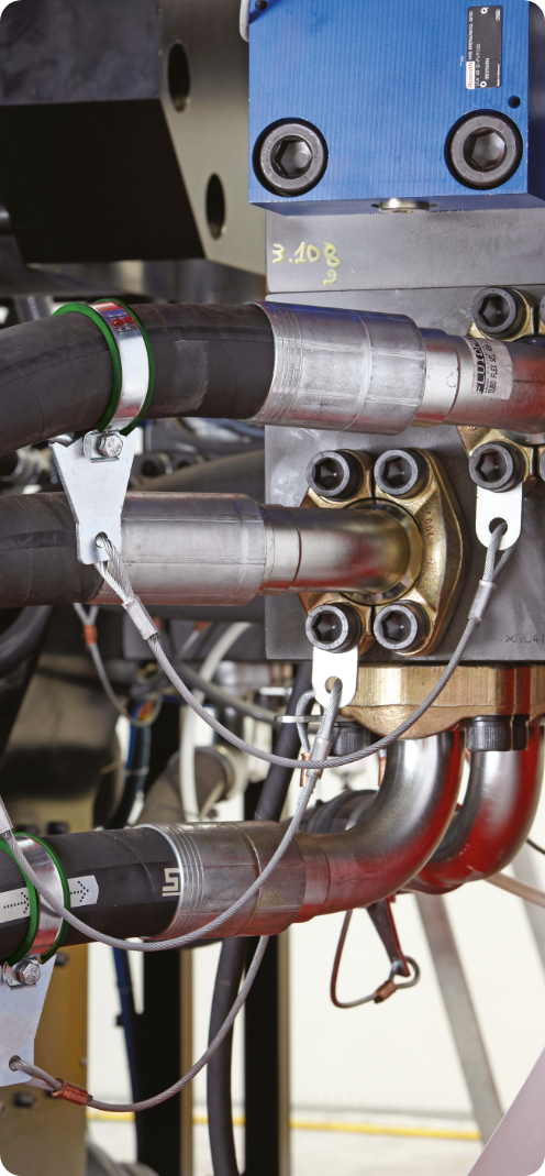
The assembly procedure of the application is fundamental to ensure the correct operation of the Stopflex system. As a matter of fact, failure to carefully follow the assembly instructions, can jeopardise the operation of the system. After numerous tests on our test benches, we found the ideal combination of materials and assembly procedure to ensure the utmost efficiency of the system.
4 fundamental aspects
- 1
Given environmental conditions such as ultraviolet light, ozone, salty water, chemical agents (solvents, fuels, oils, greases, volatile chemical compounds, acids, disinfectants and other aggressive elements) can cause early deterioration of the band seal;
- 2
The seal must be replaced every 4 years if the band is not assembled;
- 3
The seal must be replaced every 2 years if the band is assembled;
- 4
The STOPFLEX system must never be re-used in case of rupture, slip-off or replacement of the hose, as this will jeopardise the initial safety features of the system. Should the system be re-used, the assembler will be held entirely liable therefor.
NOT SUITABLE FOR HIGH PRESSURE AIR AND COMPRESSED GAS HOSES
N.B. On the market there are hydraulic flexible hoses capable of exceeding the pressures indicated in this catalogue. In case you encounter such hoses, please contact our technical department for further ascertainment regarding application thereof.
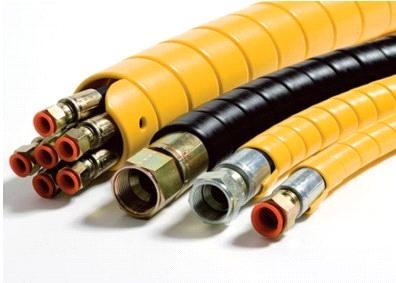
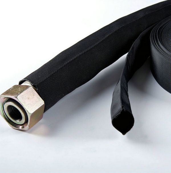
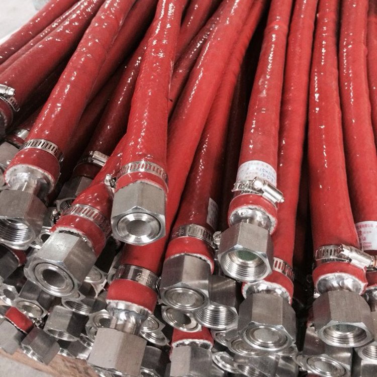
HYDRAULIC HOSE COVERINGS WHERE STOPFLEX IS NOT SUITABLE
While Stopflex is an effective solution for securing hydraulic hoses in many applications, it is not suitable for use with hoses that have the following types of protective coverings:
- 1.
High-density polyethylene (HDPE) spiral protection
- 2.
Polyester fabric protective sleeves
- 3.
Silicone-coated fiberglass protective sleeves (flame-resistant)
- 4.
PVC protective sleeves

OP S.r.l. - Via del Serpente, 97 - 25131 Brescia (Italy) - Registro Imprese Brescia / CF: 01284460175 - VAT: 03244960179 REA BS 257920 Share capital Euro 102,960.00 fully paid